Shop drawings support fabrication
They provide organized dimensions, materials, profiles, connections, and detail views that can be reviewed before production begins.
Comparing shop drawings and 3D models in metal fabrication is not about choosing one format for every project. Shop drawings communicate dimensions, profiles, materials, connections, and fabrication instructions, while 3D models help project teams understand geometry, spatial relationships, complex assemblies, and potential coordination conflicts. Many successful custom metalwork projects use both.
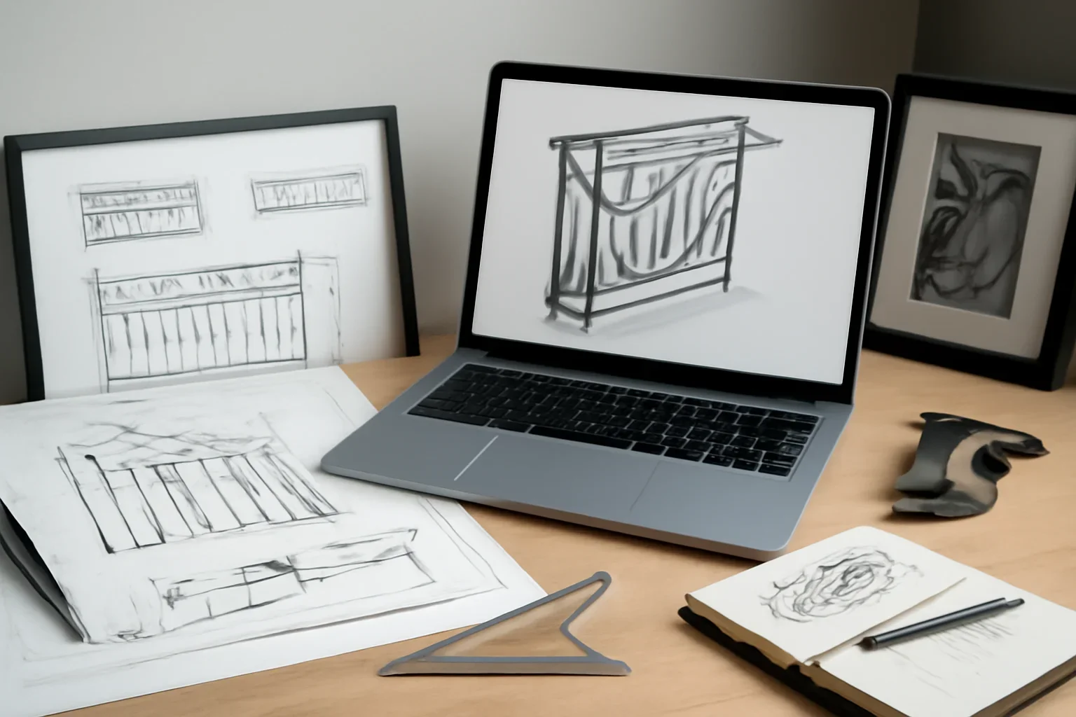
Shop drawings are detailed project documents that communicate what will be fabricated and how individual components relate to the approved design. They commonly show dimensions, material profiles, plates, welds, fasteners, hardware, connections, sections, elevations, finish notes, and interfaces with surrounding construction.
A 3D model represents the metalwork as a three-dimensional assembly. It can make complex geometry easier to understand, reveal relationships between components, support spatial coordination, and help teams review how stairs, railings, doors, canopies, screens, or structural elements fit within the building.
A 3D model improves visualization, but it does not automatically replace the dimensional and fabrication information required in shop drawings.
They provide organized dimensions, materials, profiles, connections, and detail views that can be reviewed before production begins.
They help project teams understand spatial relationships, curved forms, changing elevations, intersecting assemblies, and difficult installation conditions.
A coordinated model can help develop and review the concept, while approved shop drawings communicate the detailed information needed for fabrication.
A simple wall-mounted handrail may be communicated effectively through measured elevations, sections, and connection details. A multi-level feature staircase, curved railing, oversized entry system, or complex canopy may benefit from a coordinated 3D model before fabrication drawings are finalized.
The decision should reflect the geometry, number of interfaces, level of architectural visibility, approval needs, field conditions, and potential cost of discovering a conflict during fabrication or installation.
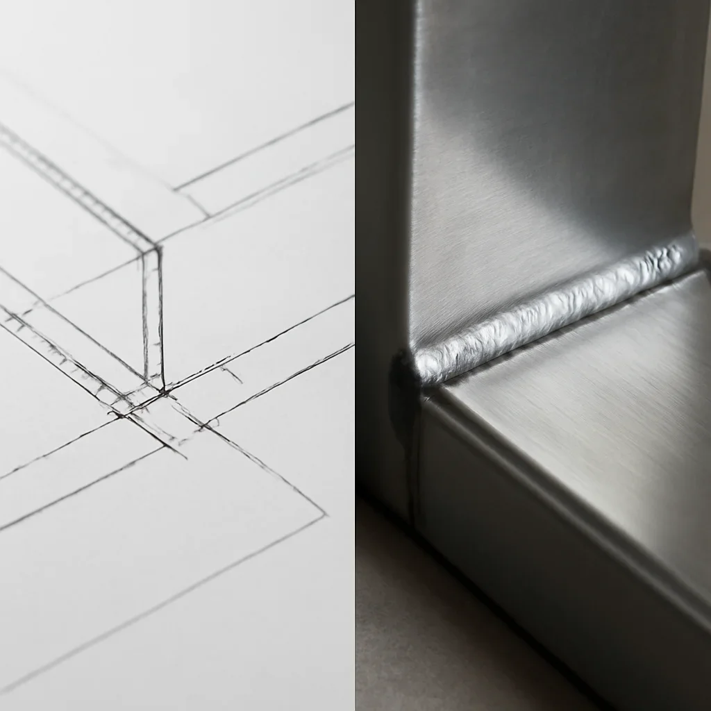
The exact drawing package depends on the feature and contractual scope. A useful set should communicate enough information for the relevant project team to understand the proposed fabrication, review interfaces, identify open questions, and approve the work before production.
Plans and elevations can define lengths, heights, widths, opening sizes, post locations, panel divisions, stair geometry, and component placement.
Drawings can identify tube, bar, plate, angle, channel, sheet, pipe, and other profiles used throughout the assembly.
Enlarged views help explain connections, transitions, brackets, mounting plates, edge conditions, hardware, and material interfaces.
Welds, fasteners, anchors, bolts, plates, hinges, brackets, and concealed supports should be coordinated with the receiving structure.
Material preparation, coating direction, color, sheen, texture, visible weld treatment, and touch-up assumptions may be documented.
The drawings can show relationships with glass, wood, concrete, stone, flooring, framing, cladding, waterproofing, and electrical components.
A 3D model can help the team see the metalwork as an assembly rather than interpreting each plan, elevation, and section separately. This is particularly valuable when the geometry changes in several directions or when components interact in a tight space.
Designers, owners, builders, and installers can more easily understand how the metalwork occupies the space and relates to nearby construction.
Curved stairs, helical rails, sloped panels, compound angles, irregular screens, and changing elevations can be easier to coordinate in three dimensions.
A model may reveal conflicts with framing, glazing, walls, ceilings, lighting, mechanical systems, millwork, or installation clearances.
Teams can review whether the fabrication should be built as a complete unit, several modules, removable panels, or smaller site-connected pieces.
Three-dimensional views can help nontechnical reviewers understand the proposed work before approving profiles, proportions, and major relationships.
The model can help examine access, lifting orientation, connection sequence, temporary support, and how components reach their final positions.
A well-developed 2D drawing package may be sufficient when the geometry is straightforward, dimensions can be clearly verified, interfaces are limited, and the assembly can be understood through plans, elevations, sections, and enlarged details.
Straight or gently changing handrails may be communicated through elevations, sections, bracket details, mounting conditions, and verified dimensions.
Straight balcony, landing, porch, or deck railings may not require full 3D development when all transitions and connections are clear.
Rectangular frames, brackets, posts, supports, and repeated components can often be defined efficiently through conventional fabrication drawings.
Repeated screen or railing panels may need one carefully detailed typical assembly plus schedules showing project-specific dimensions.
Projects with clear mounting surfaces and few connections to glass, stone, wood, or other trades may be easier to coordinate in two dimensions.
Reliable architectural and structural information can reduce uncertainty when the proposed metalwork is geometrically simple.
A 3D model becomes more useful as geometry, trade coordination, installation risk, architectural visibility, or the number of connected components increases.
Stringers, treads, landings, guards, handrails, glass, floor openings, and structural supports can be reviewed as one coordinated assembly.
Curves that change in plan and elevation can be difficult to communicate through isolated two-dimensional views alone.
Slopes, drainage, glazing, frames, columns, wall connections, lighting, signage, and cladding interfaces may benefit from model coordination.
Feature doors, sidelights, transoms, canopies, screens, access controls, and surrounding architectural details can be reviewed together.
Renovations with sloping floors, uneven walls, changing openings, or several existing materials may require deeper spatial coordination.
Models can help review whether a component can be transported, rotated, lifted, assembled, and connected within the available space.
Drawings and models are most valuable when they support decisions before the shop begins cutting and welding. They should help resolve geometry, responsibilities, interfaces, materials, visible details, finishes, and installation strategy.
Early design-assist preconstruction support can help determine whether a project needs conventional shop drawings, coordinated 3D development, or a combination of both.
A detailed shop drawing or 3D model can still produce a poor fit when it is based on outdated or assumed dimensions. Existing buildings frequently contain uneven walls, changed floor levels, altered framing, nonstandard openings, and layers of previous renovation work.
Proper site measurement and field verification helps confirm the real conditions that the drawings and model must represent before the fabrication is released for production.
Width, height, depth, floor level, slope, alignment, and nearby obstructions can affect the complete assembly.
Walls, slabs, framing, beams, columns, stairs, decks, and landings should be reviewed where the metalwork will connect.
Flooring, stone, tile, wood treads, wall finishes, decking, and cladding can change the final dimensions and edge conditions.
Doorways, corridors, elevators, stairs, landscaping, glazing, ceilings, and occupied areas can restrict component size and movement.
Field verification can identify conditions that no longer match early architectural, structural, or renovation drawings.
Measurements should occur after the relevant construction has reached a sufficiently stable and reliable stage.
Gather architectural drawings, structural information, reference images, project requirements, and available site documentation.
Use 2D or 3D tools to establish profiles, component relationships, proportions, clearances, and the overall assembly.
Review structure, glazing, walls, floors, stone, wood, lighting, hardware, waterproofing, and installation access.
Update the drawing and model information with reliable site measurements when the relevant building conditions are ready.
Generate plans, elevations, sections, connection details, material information, finish notes, and other production documents.
Confirm dimensions, geometry, interfaces, materials, responsibilities, finishes, revisions, and installation assumptions before fabrication.
Metal fabrication projects across Washington and Oregon range from urban renovations and commercial storefronts to hillside homes, waterfront properties, mountain residences, hospitality spaces, and new custom construction.
Older buildings, limited staging, narrow access, active occupants, existing finishes, and uncertain framing can increase the value of accurate field documentation.
Highly visible stairs, railings, glass, doors, and mixed-material features may require closer coordination of proportions and architectural details.
Entry systems, canopies, guards, stairs, and storefront improvements may require coordination around business access and phased installation.
Long travel distances, snow, temperature changes, transportation planning, and exterior installation conditions may affect fabrication and assembly decisions.
Difficult access, wind, salt-influenced exposure, sloped sites, and view-sensitive railings can increase coordination requirements.
Models and drawings may need to support temporary access, trade sequencing, security, public circulation, and limited installation windows.
The answer depends on who is reviewing the project and what they need to approve. A designer may need to evaluate proportions and visible relationships. An engineer may focus on members and connections. A contractor may need mounting information and interface dimensions. An owner may understand the concept more easily through three-dimensional views.
Approval should be tied to clearly identified information. A visually approved model does not necessarily mean that every dimension, connection, material, or finish detail has been approved for fabrication.
Fabricators need clear, controlled information that can be used to cut, form, fit, weld, assemble, finish, package, and install the metalwork. A 3D model can support this work, but production often still requires dimensioned drawings, detail views, schedules, material information, and fabrication notes.
Component lengths, angles, profiles, plate dimensions, holes, and part relationships must be communicated accurately.
The team needs to understand joint locations, access, alignment, visible weld expectations, distortion risks, and assembly sequence.
Hinges, locks, anchors, glass hardware, operators, fasteners, and other items must fit the fabricated assembly.
Seams, welds, edges, drain openings, masking areas, hardware zones, and surface expectations may affect shop production.
Documentation should identify which components are shop assembled, shipped separately, or connected during installation.
The fabrication team must know which drawing and model versions are current and approved for production.
A visual model may communicate appearance without providing accurate dimensions, material sizes, connections, tolerances, or fabrication details.
Detailed documentation can still be wrong when it is based on preliminary drawings rather than verified building conditions.
Conflicting information can reach the shop when the drawing package and 3D model do not reflect the same approved revision.
Excessive detail can increase time and confusion without helping design review, fabrication, coordination, or installation.
The project should clarify who provides design, engineering, measurements, drawings, modeling, approvals, and installation information.
A fully coordinated assembly may still be impractical when it cannot be delivered, moved through the building, lifted, or connected safely.
Drawings and models should connect to discovery, measurements, engineering, material selection, fabrication, finishing, delivery, installation, and final review.
Understanding the complete custom metal fabrication process helps project teams recognize when documentation should be developed, verified, approved, revised, and released to the shop.
No. Architectural drawings communicate the building design and project intent. Shop drawings focus on how a specific fabricated system or component will be detailed, coordinated, and produced.
Not automatically. A model may communicate geometry and relationships, but fabrication may still require dimensioned plans, elevations, sections, connection details, material information, finish notes, and approval records.
No. Straightforward railings, handrails, frames, brackets, and repeated panels may be communicated efficiently through a well-developed two-dimensional drawing package.
It is especially useful for feature stairs, curved railings, complex canopies, irregular geometry, mixed-material assemblies, difficult trade interfaces, and restricted installation conditions.
The reviewing parties vary by project and may include the architect, engineer, contractor, owner, designer, consultant, or another responsible professional. Approval responsibilities should be defined in the project scope.
Preliminary drawings may begin earlier, but final fabrication information should incorporate reliable field dimensions when the project depends on existing or changing site conditions.
Yes. A coordinated model can help review component size, lifting orientation, assembly sequence, access restrictions, nearby construction, and potential spatial conflicts.
Review dimensions, profiles, materials, connections, interfaces, hardware, finishes, visible details, responsibilities, field conditions, revisions, and installation assumptions.
The conflict should be resolved before fabrication. The project team must identify which document governs and update the affected files so the production information is consistent.
Yes. Documentation requires time and coordination, but it can also reduce uncertainty, field changes, fabrication errors, material waste, installation delays, and approval problems.
Share what you are planning, where the project is located, and what stage it is in. Include available drawings, digital models, site photographs, approximate dimensions, material preferences, and the fabrication or installation questions that remain unresolved.
Share your project type, Washington or Oregon location, geometry, available documentation, building stage, review requirements, and installation constraints.